


Readily Available 3D Microscopy Imaging System with Variable Focus Spinner
Summary
A large open aperture in an optical system can capture high-resolution images but yields a shallow depth of field. In order to keep the high-resolution and enlarge the DOF at the same time, back-and-forth movement of the lens should be driven by the rack and pinion motion of a motor.
However, continual forward and reverse rotation is a high-power-consumption task, because positive and negative current are used alternately to control the motor, which quickly triggers a safety stop to prevent overheating. Moreover, it is quite difficult to achieve high-speed responses in such conditions.
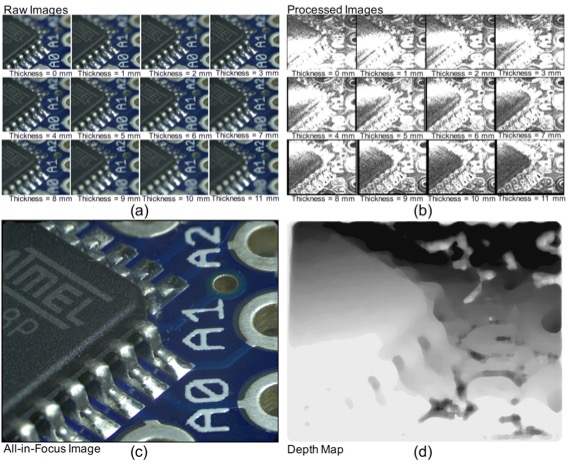
To overcome those issue, we investigated a low-cost, readily available method for retrofitting microscopy imaging systems to achieve 3D focus scanning in this study. Specifically, a procedure for fabricating variable focus spinners with dissimilar plates was introduced, and a sequence of 12 images was captured in different focal planes. The image scale and phase were corrected, and the in-focus pixels were abstracted by employing the Laplacian operator. Finally, an all-in-focus sharp image was generated, and a depth map was obtained.
The basic principle of the developed system is useful as a reference, and users could easily build their own spinners and modify and redesign the parameters for specific purposes. This design has a wide variety of potential applications, including in biomedical imaging, chip inspection, 3D sensing, and 3D printing, among other areas.
|
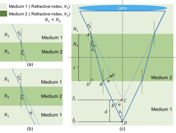
| Figure 1. Illustration of the law of refraction. (a) Basic refraction scenario, where the ratio between the sines of the angles of incidence and refraction is equal to the ratio between the indices of refraction of the two media. (b) A light beam passes through a transparent plate with a certain index of refraction and is refracted twice: when it hits the upper boundary and when it passes through the lower boundary. The final light beam is parallel to the incident beam but is shifted by a certain amount. (c) Extension of the focal length from f1 to f2 by placing Medium 2 in front of a lens, given that N2 > N1. |
|---|
|
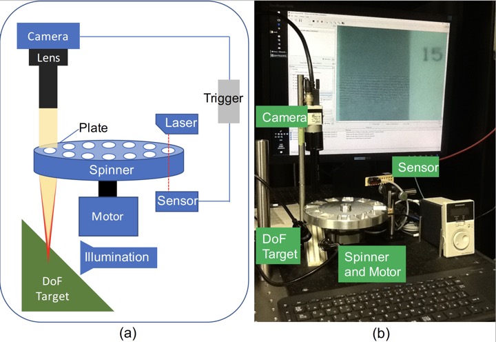
| Figure 2. Experimental setup. (a) Sketch of the setup of the variable focus imaging system. (b)Photograph of the experimental setup. The variable focus spinner had 12 apertures that were mounted with different transparent plates. |
|---|
|
| Figure 3. Images obtained by changing the plate thickness from 0 mm to 11 mm. (a) Raw image sequence. (b) Images obtained after rescaling, phase correction, and Laplacian edge detection. (c) All-in-focus sharp image generated by merging the in-focus pixels. (d) Depth map produced by using the index numbers of the images, which contained depth information. |
|---|
References
- Lihui Wang, Jianjiang Cui, Satoshi Tabata, Masatoshi Ishikawa, Low-cost, readily available 3D microscopy imaging system with variable focus spinner, Optics Express, Vol.26, Issue 23, pp. 30576-30587 (2018).[PDF(73.9MB)][DOI:10.1364/OE.26.030576] *OSA
*OSA © 2018 Optical Society of America. Users may use, reuse, and build upon the article, or use the article for text or data mining, so long as such uses are for non-commercial purposes and appropriate attribution is maintained. All other rights are reserved.