


High-Speed Focusing Vision
Summary
Although dynamic control of the optical characteristics is an important function in computer vision, the response time of the conventional optical system is too slow (>0.1 s). To solve this problem, we developed a high-speed liquid lens, called a Dynamorph Lens (DML), that achieved both millisecond-order response speed and practical optical performance. A computer vision system equipped with the DML can dynamically control its optical characteristics based on acquired images. In particular, if the total period for image acquisition and processing is matched with the response time of the DML, dynamic and adaptive control of the optical characteristics can be achieved without any loss of bandwidth. Thus, we propose a new vision system, called the {\it high-speed focusing vision system}, composed of high-speed image processing technology and a high-speed lens system based on the DML. State-of-the-art high-speed computer vision systems can acquire and process one image in 1 ms, which is almost matched with the period of the lens system (~ 2 ms).
To validate the concept of High-Speed Focusing Vision System, we developed a prototype system composed of an imaging optical system with a DML, a high-speed image processor system for high-speed visual feedback, a high-speed camera to record images at high frame rate for monitoring, and a personal computer (PC) to control the whole system. Using this prototype system, a high-speed autofocusing experiment and a focus tracking experiment were demonstrated.
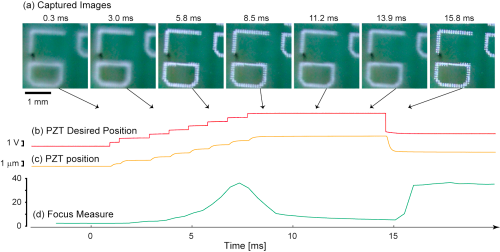
Autofocusing is an essential function for modern imaging systems. One common method is contrast measurement, which finds the best focus position by detecting the maximum contrast of images. The contrast method needs to acquire two or more images at different focus positions and evaluate their contrast. Since the focusing speed of conventional optical systems is slow, the autofocusing process tends to take a long time (typically ~ 1 s). This problem could be solved by our high-speed focusing vision system. Thus, we implemented the contrast method of autofocusing in the prototype system. Figure 1 shows the result of the autofocusing when the object was the surface of an electronic substrate. The focus scanning process started at t=0 ms and finished at around t=14 ms. The peak of the focus measure was observed at about t=7.5. After the focus scanning process, the focus was controlled to the estimated correct focus position. The entire autofocus process finished at t=15.8 ms. Note that the total autofocus period of 15.8 ms is shorter than the typical frame period (30 to 40 ms) of conventional vision systems.
Next, a dynamic focus control experiment was conducted. The purpose of this experiment was to track the correct focus for a dynamically moving object. For this purpose, a quick estimation of the target depth is important. Thus, we developed a technique that vibrates the object plane position around the target. Three images were captured at near, correct, and far focus positions and their focus measures were measured to estimate the object's depth. Then, the center of the vibration was adjusted to be the object position estimated from the latest three focus measures. Experimental results of focus tracking are shown in Figure 2. The focus tracking was started at t=0. From the images captured by the high-speed camera (Figure 2 (b)), the image was successfully kept in focus.
|
| Figure 1. Experimental results for high-speed autofocusing of an electronic substrate. (a) Image sequence captured by the high-speed camera at 2200 fps. (b) Instruction voltage input to the piezostack actuator. (c) Displacement of the actuator measured by a built-in sensor. (d) Focus measure (Brenner gradient) calculated by the PC. |
|---|
|
|
| Figure 2. Results of the high-speed focus tracking experiment. Upper row shows an image sequence without focus tracking (a), and lower row with focus tracking (b). |
Movies
References
- Hiromasa Oku and Masatoshi Ishikawa : High-Speed Liquid lens for Computer Vision, 2010 IEEE International Conference on Robotics and Automation (ICRA 2010) (Anchorage, 2010.5.5) / Conference Proceedings, pp.2643-2648 [PDF (1.6MB)]*IEEE
- Hiromasa Oku and Masatoshi Ishikawa : High-speed liquid lens with 2-ms response and 80.3-nm root-mean-square wavefront error, SPIE Photonics West 2010 (San Francisco, 2010.1.25) / Proceedings, 7594-05 (Oral Session) [PDF (2.1MB)]
- Hiromasa Oku and Masatoshi Ishikawa : High-speed liquid lens with 2 ms response and 80.3 nm root-mean-square wavefront error, Applied Physics Letters, Vol.94, 221108 (2009) [PDF (312K)] [doi:10.1063/1.3143624] *AIP
- Hiromasa Oku, Masatoshi Ishikawa : Rapid Liquid Variable-Focus Lens with 2-ms Response, 19th Annual Meeting of the IEEE Lasers & Electro-Optics Society (Montreal, 2006.11.2)/Proceedings pp.947-948 [PDF (527K)] *IEEE
*AIP © 2009 American Institute of Physics. This article may be downloaded for personal use only. Any other use requires prior permission of the author and the American Institute of Physics. The article appeared in H. Oku et al.,Appl. Phys. Lett. 94, 221108 (2009) and may be found at http://link.aip.org/link/?APL/94/221108.
*IEEE © 2006-2010 IEEE. Personal use of this material is permitted. However, permission to reprint/republish this material for advertising or promotional purposes or for creating new collective works for resale or redistribution to servers or lists, or to reuse any copyrighted component of this work in other works must be obtained from the IEEE.