| |
Smart Laser Scanner for Human-Computer Interface |
| Japanese version is also available. | (images in this page may be subjected to copyrights) |
[Read short article featured at DiscoveryChannel.com (News)] | 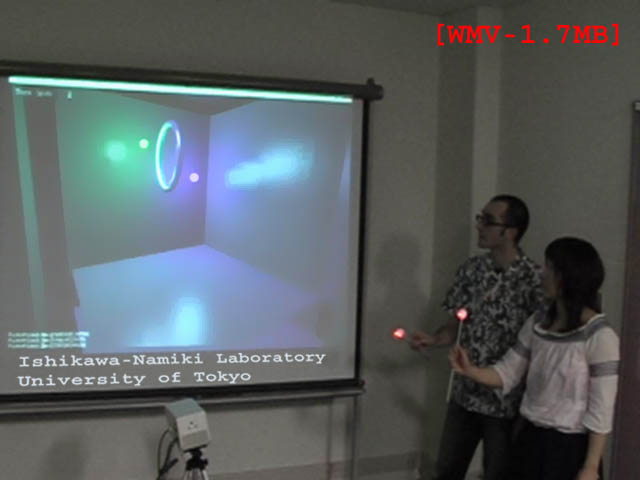 |
|
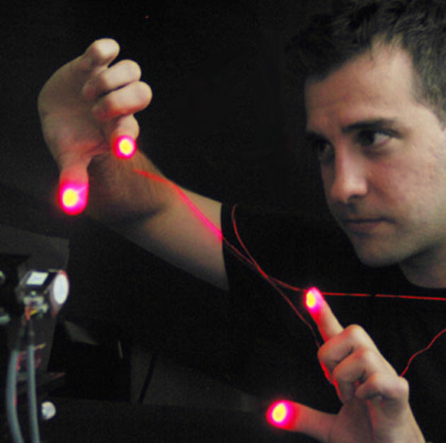
The problem. Input of information is becoming a challenging task as portable electronic devices become smaller and smaller. Alternatives to the keyboard/mouse are necessary on handheld computers; for instance, on personal digital assistants (PDAs), input of text data is often done through a touch sensitive screen and a stylus using a prescribed input method, such as Graffitti™. The input space is thus merged with the viewing space, allowing a substantial saving of physical space. The next logical step would be to remove the need for any (dedicated or merged) input space, as well as the need for any additional input device (stylus, data-gloves, etc). This would allow inputting data by just executing bare-handed gestures in front of a portable device - that could then be embodied in a keyboardless wrist-watch. Ultimately, coupling such interface with a projective display (e.g. an eyeglass-mounted display or even a laser-based display) capable of creating an arbitrary large virtual space would completely remove the need of any real interaction area (for viewing or inputting data), allowing further downsizing of mobile computing devices (see figure). Our approach. The problem of tracking hands and fingers on natural scenes has received much attention using passive acquisition vision systems and computationally intense image processing. We are currently studying a simple active tracking system using a laser diode (visible or invisible light), steering mirrors, and a single non-imaging photodetector, which is capable of acquiring three dimensional coordinates in real time without the need of any image processing at all. Essentially, it is a smart rangefinder scanner that instead of continuously scanning over the full field of view, restricts its scanning area, on the basis of a real-time analysis of the backscattered signal, to a very narrow window precisely the size of the target. |
|
 |
The proposed active-tracking mechanism has some appealing features over other conventional (passive or active) tracking systems:
|
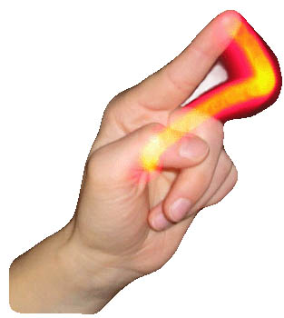
Tracking is based on the temporal analysis of the backscattered light measured during a millisecond-long circular laser saccade generated around the current position of the tracked object, thanks to a beam-steering mechanism. Adaptive saccade shapes are also under study (these would change so as to match important features of the tracked object). The figure shows a simplified, step-by-step tracking sequence. |
Since the scan has a finite duration and the object cannot be expected to wait for the scan to complete, there is a systematic drift on the computed recentering vector. Thanks to elementary prediction strategies (e.g. Kalman filtering), this drift can be readily eliminated. Additional processing is required to adjust the size of the saccade as the object moves back and forth from the tracking system, or, for instance, to maintain the tracking of a fingertip without seeing the saccade slipping towards the base of the finger - but this additional processing remains elementary.
| |
|
||
(a) The saccade is supposed to remain fully inside the object while tracking;(b) As the object moves, a small portion of the saccade may fall outside the object, and the backscattered signal will momentarily drop. Due to the synchronous operation of the beam-steering mirrors and the photodetection, an accurate recentering vector (blue arrow) is computed.(c) The center of the saccade is updated accordingly. These three steps are repeated continuously (each circular scan takes about one or two milliseconds). |
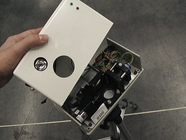
Beam Steering mechanism: The beam-steering mechanism represents the critical part of the system, determining both the ultimate tracking performance and the compactness of the whole setup. In our proof-of-principle experiment, a pair of high-performance closed-loop galvano-mirrors with axes perpendicular to each other (GSI Lumonics, Model V500) are used for both generating the saccade and performing the actual tracking. The galvano-mirrors have a typical clear aperture of 5 mm and a maximum optical scan angle of ±50 Decoupling the mechanism responsible for the saccade generation from the mechanism used to actually keep track of the object position can lead to optimal tracking speeds (for instance, acousto-optic deflectors or resonant micro-mirrors can be used to generate Lissajou-like saccade patterns, while slower but precise micromirrors are used to position the center of the saccade).
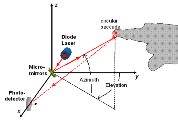 |
Laser source: The laser source is a focusable (20 mm/inf) diode laser delivering a maximum optical power of 1 mW at a peak wavelength of 633 nm (this power/wavelength corresponds to a Class II laser source, similar to that of a barcode scanner, and in normal conditions does not represent any hazard to the eye). Since the target is likely to represent a small portion of the total field of view, the illuminating energy can be efficiently concentrated, and therefore the system will be extremely power-efficient and work equally well with distant targets. In our experiments, 1 mW was enough to produce a good signal-to-noise contrast up to two meters away from the system. Since the backscattered signal originates by isotropic diffusion/reflection on the skin surface, the necessary optical power scales as the square of the working distance; therefore, for distances less than 10cm (typical of portable devices) the required optical power would drop below 30microW. Visibility of the source greatly simplifies the calibration of the system, but in a final system, an invisible (thus less interfering) eye-safe far-infrared (>1400 nm) laser diode may be preferred. |
|
 |
 |
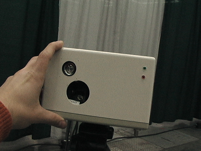 |
Photodetection: In the present setup, a wide-angle photodetector placed in the neighborhood of the beam-steering mechanism collects all the light from its surroundings. Thanks to synchronous photo-detection, this system is insensitive to harsh or changing lighting conditions (a wavelength filter seemed unnecessary). The laser is modulated at around 40kHz (which is the Lock-In amplifier reference TTL-compatible square signal). To avoid saturation as well as large noise when the finger is close to the system, the average laser power is also modulated so as to always have the same optical power on the photodetector (this eliminates the need of a noisylogarithmic amplifier). It is interesting to note that the overall complexity of the setup is equivalent to that of a portable laser-based barcode reader. |
||
 Tracking precision.
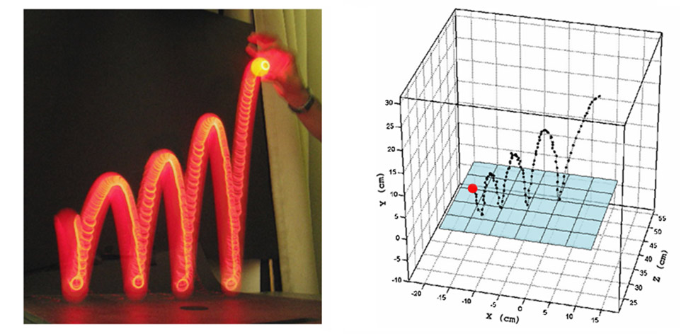
 Using the simple "closed-loop" tracking mechanism described above, a tracking resolution of about 0.2ー (or 3 mm at a distance of one meter) was achieved in a prototype tracking system using off-the-shelf electromagnetic-actuated micro-mirrors (mirror excursion is ±52ー, leading to an optical excursion range of ±50ー both on X and Y axis). Depth is computed at the end of each saccade from the averaged intensity of the backscattered signal - which evolves roughly as the inverse square of the distance. Discrimination between the tracked object (e.g. fingertip) and the background (including other parts of the hand) is possible as long as the signals present enough contrast. By modeling the various sources of noise, we estimated and later verified that, without resorting to synchronous photodetection nor any signal post-processing, the prototype is already capable of sub-centimeter depth discrimination at a distance of up to 30 cm (with 90% confidence), and has a peak resolution of less than 4 mm at a distance of 5 cm from the system [3]. Using synchronous photodetection, we achieved 1 cm detph resolution at least up to 2 meters [1]. /p>
The dynamic performance of the system was evaluated by measuring the maximum speed an object could move without being lost by the tracking system. The tracked object was a circular piece of white paper, 9 mm in radius, tracing a circular trajectory at different uniform speeds. The distance between the mirrors and the object remained constant. Maximum tracking speed was measured to be around 3 m/s at a distance of about one meter from the mirrors (the typical speed of a finger performing gestures is < 2.5 m/s), and was only limited by the speed of the A/D interface cards [2][3]. It is interesting to note that, since in the present system the angular speed of the mirrors is not a limiting factor, for an object of a given size and assuming that the saccade radius is always properly adjusted to it, its distance from the tracking system has no effect on the tracking speed.
|
|
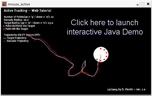
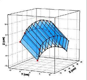
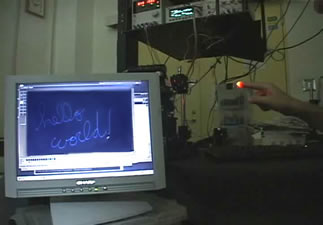 Assuming
that the plane of the gesture, though forming an arbitrary angle with
the system axes, remains stable during the acquisition of a single
character written on the air, it is possible to project the acquired 3D
data over a real-time estimated best fitting hyperplane, thus preparing
the data for feeding in a "traditional" 2D character recognition
algorithm (click here on on the figure on the right for a video demo). Some experiments on character recognition using
this system and Hidden Markov Models (HMMs) can be found in [3].
Assuming
that the plane of the gesture, though forming an arbitrary angle with
the system axes, remains stable during the acquisition of a single
character written on the air, it is possible to project the acquired 3D
data over a real-time estimated best fitting hyperplane, thus preparing
the data for feeding in a "traditional" 2D character recognition
algorithm (click here on on the figure on the right for a video demo). Some experiments on character recognition using
this system and Hidden Markov Models (HMMs) can be found in [3].
In the future, the reliability of a character/word based recognition algorithm can be enhanced by fusing the three-dimensional data with that of an accelerometer bound up with the acquisition system, so to compensate in real time for motion and twisting artifacts during character acquisition. The ultimate goal is to built a constraint-free input interface for character recognition. Such an interface would enable the user to write freely on the air, without putting much attention on the relative position of the writing hand with respect to the acquisition system (e.g. on a wrist watch on the opposite hand, a portable phone or a PDA for instance), nor caring about the stability of the former. If these conditions are fulfilled, it would be possible for the user to input data while walking on the street for instance.
Of course, the use of the third dimension could allow switching between different modes, such as from character input mode to a mouse-like mode (where a pointer is moved according to the finger movement). Alternatively, in drawing application, switching from a pencil tool to an eraser tool, for example, is possible. More interestingly, the third dimension can be used for more complex applications that fully make use of this feature of the system. One application could be to define a complete 3D alphabet in order to allow a more natural and richer interaction language with a machine. Another could be to allow the user to input, interact and modify 3D data in CAD applications.
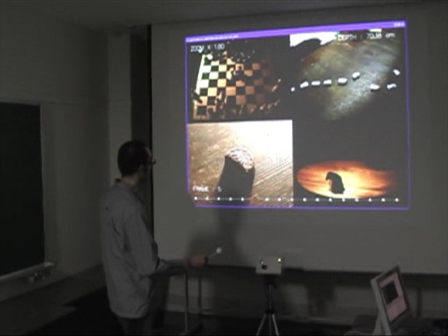
| Lastly, 3D tracking of fingers and hands can simplify or completely redefine the way some typical GUI task are performed, such as moving around or controlling the zooming of a map (see video demo - the system works with bare fingers, but white balls are used as scaled-up models of the fingertip, to enable tracking at longer distances). |
|
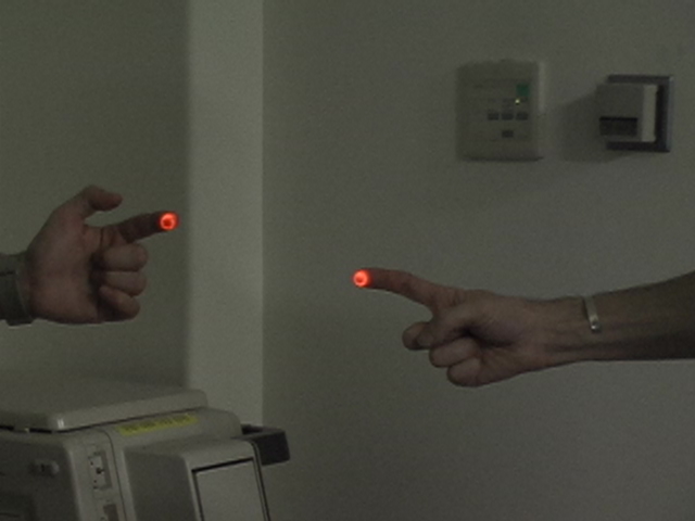
Applications of a multiple target tracking system are countless. Such a configuration allows, for instance, multiple users to interact on the same virtual space; or a single user to control several virtual tools at the same time, resize windows and control information screens, as imagined in Spielberg's film ``Minority Report'' -but without the need to wear special gloves nor markers.
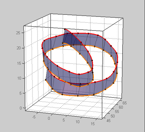
Tracking of multiple targets without replicating any part of the system was successfully demonstrated [1][2]. Targets are considered sequentially. The price to pay is a tracking slowdown for each individual target, roughly equal to the inverse of the number of targets. Additional time is required to position the mirrors from one target position to another. A particularly interesting case were tracking performance seems unaffected for all purposes, is when two fingers belonging to the same hand are simultaneously tracked; the maximum tracking speed is only roughly divided by two, which leads to 1.5 m/s tracking speed - enough for most CAD applications (see figure). |
|
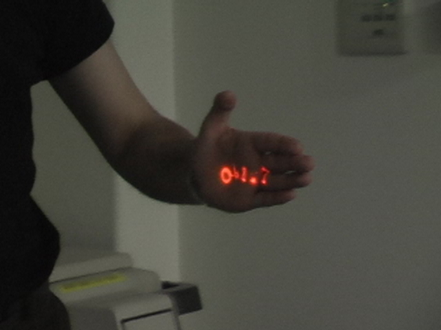 |
Last, a very interesting characteristic of the proposed 3D laser-based locator, is that it also can be used as an output device: indeed, the laser scanner can be used to write information back to the user, by projecting alphanumeric data onto any available surface, like the palm of the hand [1]. This has been succesfully demonstrated, without having to stop the tracking. |
 System on-chip integration.
The simplicity of the system is such that, using state-of-the-art
Micro-Opto-Electro-Mechanical-System (MOEMS) technology, it would be
possible to integrate the whole system on a chip, making it an
interesting input interface for portable computing devices. One or
two-axis micro-electro-mechanical micromirrors (packaged on a chip 1 cm
square in size) are already commercially available. Very similar MOEMS
have been successfully built in the past, and challenges related to the
integration of an optical source along with its beam-steering mechanism
have been addressed both theoretically and experimentally in fields as
diverse as free-space optical switching, single-chip scanners, and
automatically aligned free-space optical links. We believe that once
integrated, it will be readily accepted as a versatile input/output interface,
freeing actual physical space on mobile devices. The whole PDA could fit in a keyboardless, screenless chest pin, that when activated will follow hand gestures, and write back information on the palm of the same hand [1].
System on-chip integration.
The simplicity of the system is such that, using state-of-the-art
Micro-Opto-Electro-Mechanical-System (MOEMS) technology, it would be
possible to integrate the whole system on a chip, making it an
interesting input interface for portable computing devices. One or
two-axis micro-electro-mechanical micromirrors (packaged on a chip 1 cm
square in size) are already commercially available. Very similar MOEMS
have been successfully built in the past, and challenges related to the
integration of an optical source along with its beam-steering mechanism
have been addressed both theoretically and experimentally in fields as
diverse as free-space optical switching, single-chip scanners, and
automatically aligned free-space optical links. We believe that once
integrated, it will be readily accepted as a versatile input/output interface,
freeing actual physical space on mobile devices. The whole PDA could fit in a keyboardless, screenless chest pin, that when activated will follow hand gestures, and write back information on the palm of the same hand [1].
Incidentally, a point that can significantly add interest to the system, is that it can also be used to create an adaptive free-space optical link between portable computing devices in motion. This way a -mobile- optical network could be easily created between a team of users whenever required.
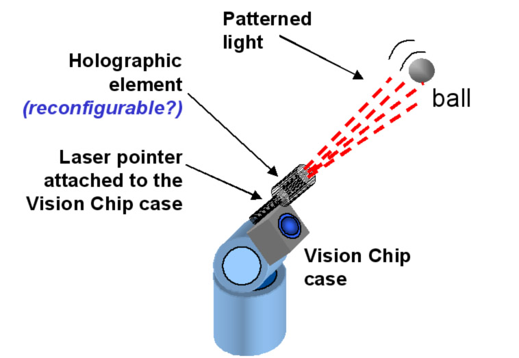
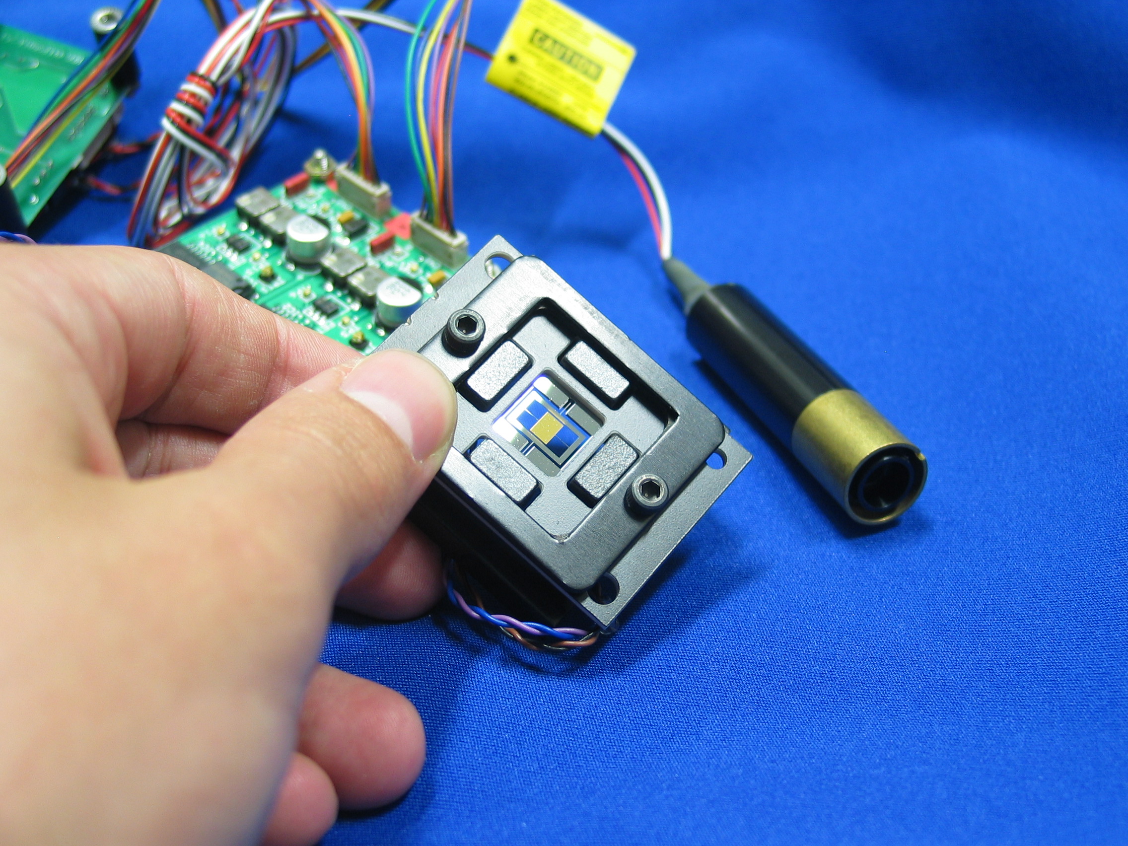
Laser-enhanced Vision Chip system. Tracking using Vision Chip is also based on a closed-loop mechanism relying both on real-time image processing and steering of the camera viewing field. However, given the extreme frame-processing rate, in its current version Vision Chip needs a relatively powerful illumination source. Superluminiscent LEDs bound up with the steereable camera module performs well in most short-range experiments. A diode laser attached to the Vision Chip module, or steered by micro-mirrors can be used even when targets are several meters away from the system. Special light patterns can be also generated (using scanning mirrors or reconfigurable holograms) opening the door to more powerful, active, Vision Chip-based applications.
Laser-Tracking system without mobile parts. Research is underway on a version of the laser tracking system without any mobile parts (such as micromirrors). This is possible using using advanced (integrable) optoelectronic components. Although tracking resolution is expected to be somehow reduced, it will presumably be more than enough for tracking gestures at a short distance from the system. Results will be published soon.
Detailed demos:
Whole system presentation and demo:
|
|
[1] - A. Cassinelli, S. Perrin and M. Ishikawa, Smart Laser-Scanner for 3D Human-Machine Interface, CM SIGCHI 2005 (CHI '05) International Conference on Human Factors in Computing Systems, Portland, OR, USA April 02 - 07, 2005, pp. 1138 - 1139 (2005). Abstract: [PDF-835KB]. Video Demo: Good Quality: [MPG-176MB], Compressed:[MPG-28MB]. Slides Presentation (click on images to launch video demos) [PPT-10MB].
[2] - A.assinelli, S. Perrin and M. Ishikawa, Markerless Laser-based Tracking for Real-Time 3D Gesture Acquisition, ACM SIGGRAPH 2004, Los Angeles. Abstract: [PDF-87KB]. Video Demo: Good Quality [AVI-24,7MB], Compressed [AVI-6,3MB]. Poster [JPG-835KB].
[3] - S. Perrin, A.assinelli and M. Ishikawa, Gesture Recognition Using Laser-based Tracking System, 6th International Conference on Automatic Face and Gesture Recognition 2004 (FG 2004), Seoul, Korea, 17-19 May 2004 [PDF-402KB]*, Poster [PPT-457KB]*.
[4] - S. Perrin, A. Cassinelli and M. Ishikawa, Laser-Based Finger Tracking System Suitable for MOEMS Integration, Image and Vision Computing, New Zealand (IVCNZ 2003), Massey Univ., 26-28 Nov. 2003, pp.131-136, (2003). [PDF-239KB]. Poster presentation [PPT-1432KB].
Alvaro Cassinelli (Assistant Professor).
Ishikawa-Namiki Laboratory - Department of Information Physics and Computing.
The University of Tokyo. 7-3-1 Hongo, Bunkyo-ku, Tokyo 113-0033 Japan.
Tel: +81-3-5841-6937 / Fax: +81-3-5841-6952
Email: alvaro@k2.t.u-tokyo.ac.jp
*IEEE © 2003 IEEE. Personal use of this material is permitted. However, permission to reprint/republish this material for advertising or promotional purposes or for creating new collective works for resale or redistribution to servers or lists, or to reuse any copyrighted component of this work in other works must be obtained from the IEEE.
[ Home | Sensor Fusion | DVS | Vision Chip | Optics in Computing | Members | Papers | Movies ]
